|
|
|
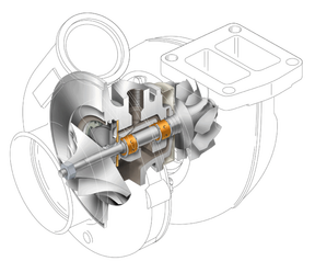
Although today we talk a lot about turbocharged engines, they aren´t a product of new technology as novel as they seem. The process of turbocharging has its history linked to aviation. Where a pressure greater than the atmospheric in the cylinders, compensated the effects of air rarity experienced at high altitudes. Along with this came an increase in engine power output , that later evolved into a valuable resource for race cars in the 50`s. Nowadays, acclaimed as a developed version of the more common naturally aspired engine, the turbocharged engine has become part of the light and heavy engines industry i.e; engines for full-size trucks, SUVs, cars, boats, motorcycles etc. The turbocharger consists of a centrifugal air compressor, directly linked to a centripetal turbine. Each wheel is linked to an axle supported by floating bearings, lodged in a bearing housing. The centripetal turbine wheel is housed in a cast iron housing; the compressor wheel in a cast aluminum housing. Bearing housings include the compressor back plate, heat shield, bearing safe rings, bearings, thrust bearings, centrifugal collar, piston rings and seal ring.
|
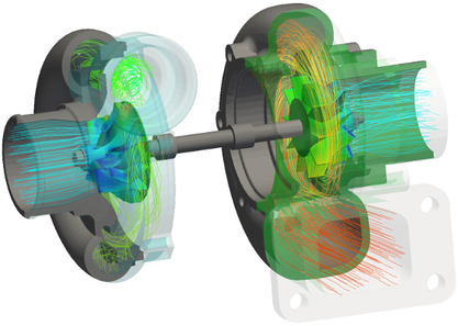
Fig. 1A: Typical 3D CFD model showing fluid flow and thermodynamic properties of a radial turbocharger.
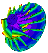
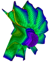
Our engineers use a variety of cutting edge modeling software packages to perform anything form a quick 1D through-flow to 2D structural mechanics, rotor-dynamics, Thermal and combustion analysis. Finally the designs are optimized through mesh generation and extensive 3D full CFD (Fig. 1A), and FEA (Fig. 1B) models some requiring tens of millions of elements to produce reliable results. These tools enable us to design every component of our turbocharger products to perform under extreme loads. They also allow us to provide the leading 1 year warranty in the business at a more than competitive price.
|
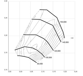
Proprietary algorithms and tools allow us to post-process the data for a quick turn-around on custom matching analysis, shorter time to market, research and development. Compressor components (i.e; Impeller, volute, diffuser, blade) as well as turbine models are designed to near null error tolerances. These tools enable us to develop turbochargers with greater transient efficiency (diminished lag), durability, enhanced compressor map widths (i.e., ported shrouds, anti-surging technologies), mixed flow turbine wheels and twin scroll turbine designs.
Fig. 1B: Typical 3D structural FEA model showing Von Mises stress distr. on a 7 blade compressor wheel and 12 blade turbine wheel under load.
|
|
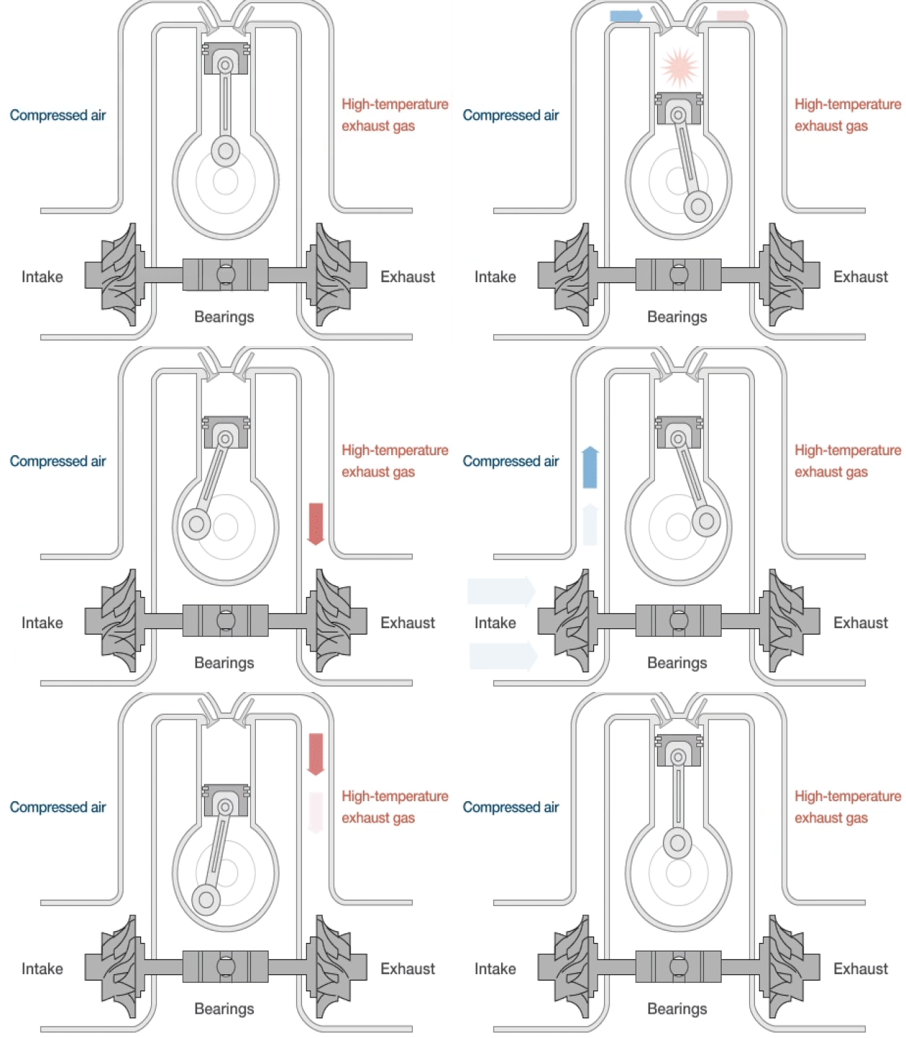
Operating Procedure- For all the energy required to produce power by the naturally aspired internal combustion engine, only one third is used to turn the engine, another third disappears in the air intake and cooling system with the remaining third being wasted as exhaust gas. The turbocharger uses the energy produced by expansion of said exhaust gases to rotate the turbine wheel, which turns at a rate as low as 3,000 RPM with a maximum speed well into the 150,00 RPM range. Joined by a common axle to the compressor wheel, that rotates at the same speed, aspiring the air through the filter and compressing it via the compressor housing into the cylinder interior.
|
|
Function- The function of the turbocharger is to provide a greater air volume to the engine, making possible a perfect fuel burning and an improvement in performance and volumetric efficiency.
Turbocharged Engine: A turbocharged engine, receives compressed air via the turbocharger`s compressor and in turn provides greater than 100% volumetric efficiency at altitudes of over 40,000 feet. Naturally Aspired Engine: Naturally aspired engines lose roughly 50% of its power every 20,000 feet. |
Benefit- A Centrifugal Turbochargers provides The following...
More Power: Adding more quantity of air in the cylinder, the engine can burn a bigger volume of fuel automatically and it has an increase of power as high as +/- 200% or more in some cases. Less Fuel Consumption: The fuel quantity consumed by a turbocharged engine is normally around 15% less than a naturally aspired one for similar power outputs. Smoke Elimination: A turbocharged engine is basically a cleaner engine. Disposing a bigger volume of air in the cylinder, assures a perfect burning of exhaust gas, avoiding the fuel waste and eliminating the smoke. |
|
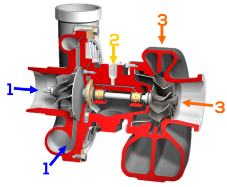
1. "Compressor housing and compressor wheel"- The centrifugal air compressor`s function is to aspire the atmospheric air and compress it to the cylinder interior, reaching over five times the atmospheric pressure in some cases. (1 atmosphere=14.696 psi)
2. "Bearing housing"- The bearing housing gets lubricant oil form the engine and serves as sustenance to the turbine and compressor wheel which floats on thrust bearings. (Journal bearing shown, Hybrid and full ceramic ball bearing similar) 3. "Turbine wheel and turbine housing"- The centripetal turbo is started by heat energy from exhaust gasses and performs the function of impelling the centrifugal compressor. |
|
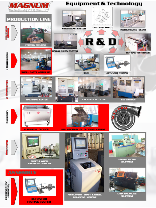
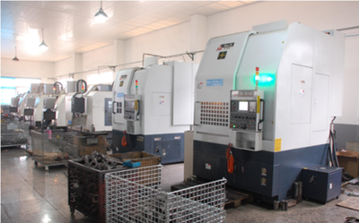
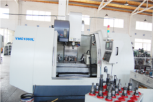
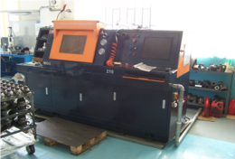
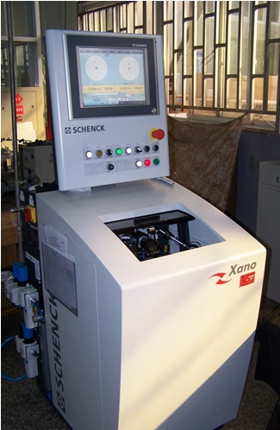
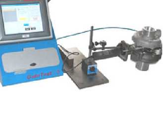
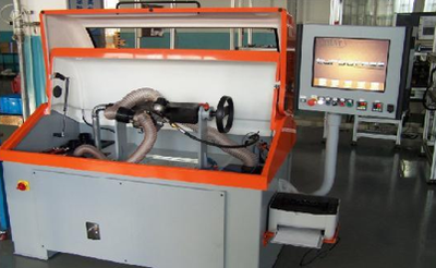
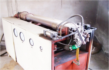
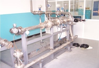
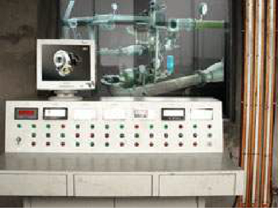
Our units are produced in a top notch Research and Development facility. Every step of the R & D process is quality controlled in accordance with American and International standards from raw material to final assembly. Production and testing equipment include top of the line Machine Centers, CNC lathes and grinding machines, Honing Machines, Vertical Lathes, Automated Grinding Machines, VSR balancing machines, Programmed Test Benches and 3-coordinate measuring machines.
|
All of our turbocharger products are available with the optional ceramic ball bearing technology and most with the latest dual ceramic (cartridge style) ball bearing CHRA. All of our products are covered by the leading One Year Warranty in the industry. We confide in our product enough to cover our units under warranty for manufacturer's defects even at the race track (limitations may apply, see warranty card for details). Our units are produced in a top notch Research and Development facility. Every step of the R & D process is quality controlled in accordance with American and International standards from raw material to final assembly. Production and testing equipment include top of the line Machine Centers, CNC lathes and grinding machines, Honing Machines, Vertical Lathes, Automated Grinding Machines, VSR balancing machines, Programmed Test Benches and 3-coordinate measuring machines.
|
Our Service Centers and Post-assembly facilities are domestically located in the Alabaster, Alabama and cutting edge. This allows us to provide a quick turnaround on warranty items and service needs while maintaining the most competitive prices in the industry. Please see our contact-us page for locations, hours of operation and contact information.


